This is a simple three-point bending instrument for measuring materials' flexural modulus. This was quickly improvised from parts on hand from other projects.
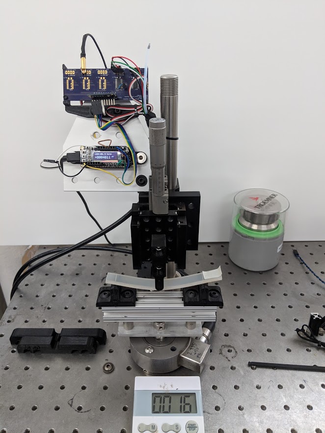
Three-point bending apparatus
Analog Front End
The load cell is amplified with a TI INA125 instrumentation amplifier that also excites the cell using its built-in precision voltage reference. I designed the custom 5 channel INA125 PCB for thruster force and torque measurements in Pliant's in-house tank, and I repurposed a spare board for this insrument. A DC-DC converter provides +/- 12V supplies from the 5V USB bus voltage that powers the microcontroller.
The large load cell used for this project had a significantly lower resistance than those I used for the torque/force measurements, so I had to add a transistor from V+ to the excitation amplifier output to boost the excitation current. The built-in excitation amplifier's feedback still maintains the excitation voltage at the appropriate level.
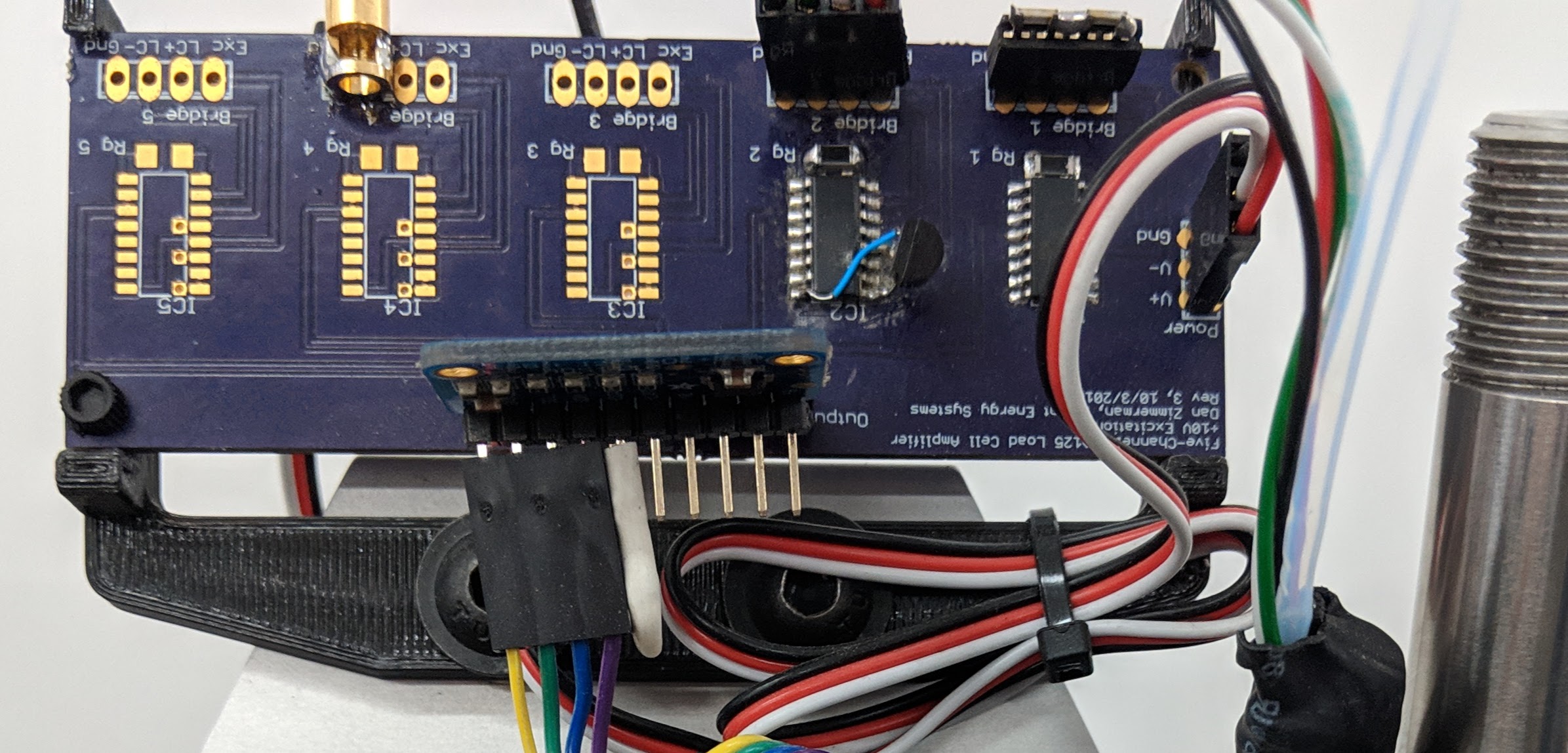
Transistor current boost and 16-bit ADC
The output of the load cell amplifier is digitized using an ADS1115 breakout board from Adafruit controlled by an Adafruit Feather M0 which displays the measured load on an OLED Featherwing display module. The A/B/C buttons take user input.
Controller
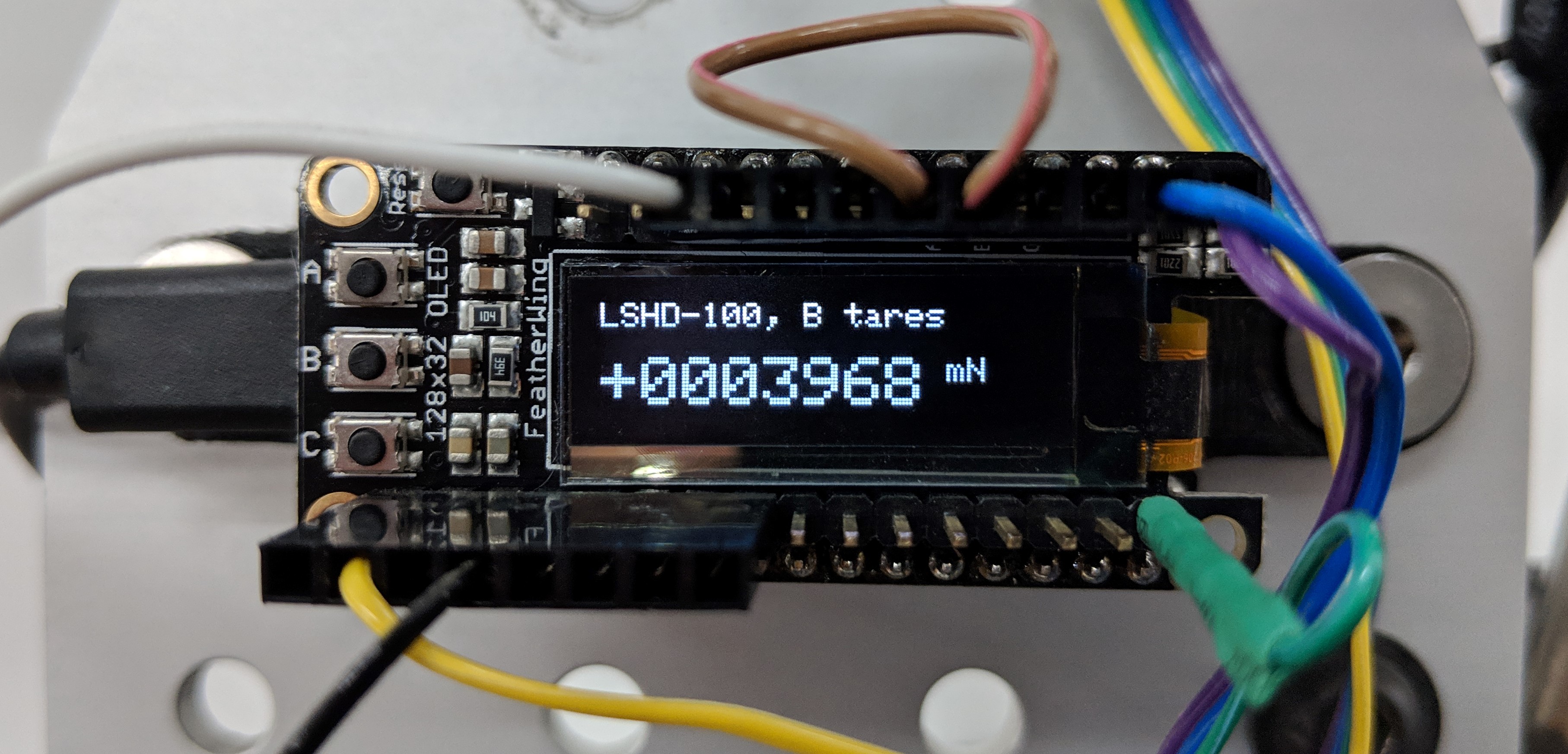
Load cell display
The firmware has several operating modes. It will display raw microvolt readings at the output of the amplifier. It will display the load in milliNewtons based on an internal calibration. And, it has a calibration mode that acquires several seconds of the 16 bit ADC integer reading on the press of a button, averages it, and displays that value until it is cleared.
This was used to manually calibrate the instrument using precision reference weights. I decided that the user should not be able to update the calibration constants from the front panel. The calibration is hard-coded, and the controller needs to be re-flashed to apply a new calibration. This is mainly to help ensure reproducibility. During the calibration procedure, the calibration data is recorded and stored alongside the flexural modulus test data, so each calibration is documented.
Mechanical Design
Radiused 3D printed fixtures are designed to the specifications of ASTM D790. The span can be adjusted to maintain the appropriate depth-to-span ratio specified in the standard. Crosshead displacement is controlled manually with a micrometer linear stage.
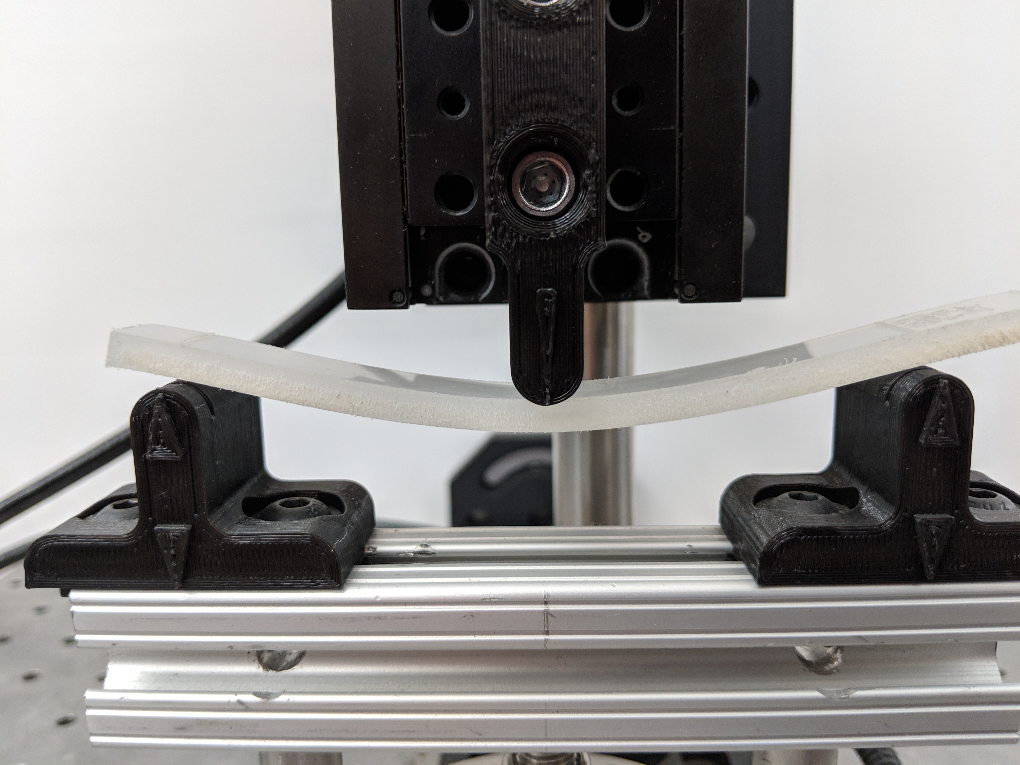
Adjustable bending fixture
A motorized stage to impose constant strain rate would be superior. However, the micrometer stages were on hand from a prior project, and the materials under test are highly elastic with low damping, so the strain-rate dependence is fairly weak. A timer is used to manually standardize the dwell time between "suddenly" imposing a displacement and recording a load measurement. The flexural modulus results agree to within a few percent with professional Instron measurements made by one of our material suppliers, and are more than adequate for quick assessments of materials.