Background
Angular momentum is a fundamental conserved quantity in fluid flows, and it is neither created or destroyed inside the fluid. It can only be added or removed from the flow by torques applied at the boundaries, so accurate measurements of boundary torques provide a lot of insight into the global flow state. To understand angular momentum transport in the UMD Three Meter Geodynamo, I designed and built a wireless sensor for high-resolution measurements of the torque on the inner sphere.
Circuit Design
Most of the instrumentation on the three meter experiment is mounted on the rotating outer sphere and communicates to the stationary laboratory frame using Wi-Fi. However, the most sensitive method of measuring the inner sphere torque was to use a strain-gauge torque sensor between the inner sphere drive motor and the shaft that drives the inner sphere. The circuit here measures the torque sensor's output and transmits it to the laboratory frame.
The millivolt-level output of a Futek reaction torque sensor is amplified with an LT1167 instrumentation amplifier and digitized with a MCP3553 22-bit analog-to-digital converter.
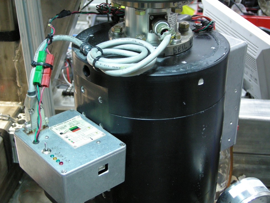
Sensor, electronics, and custom shaft coupler
An Arduino running simple firmware controls the digital data acquisition over SPI and transmits the torque data to the stationary lab frame using an XBee wireless serial connection. This design was conceived and implemented before the wide availability of miniature low-cost wireless-enabled microcontroller modules. I would recommend using something with WiFi or maybe Bluetooth or LoRa if I did this today.
The system is powered from a rechargeable Lithium Polymer battery with a DC-DC converter to provide +/- 12V rails. This supply is housed in a separate box and its output is filtered with LC filters to reduce switching noise leaving the box. Internal linear regulators are also used inside the torque sensor box to further reduce power supply noise.
In addition to developing and fabricating the electronics for this system, I fabricated the black anodized custom shaft coupler and electronics mount pictured above. I machined an aluminum lid and tube from plate and hollow bar stock, TIG welded them together, and machined the part to its final form before sending it out to be anodized.
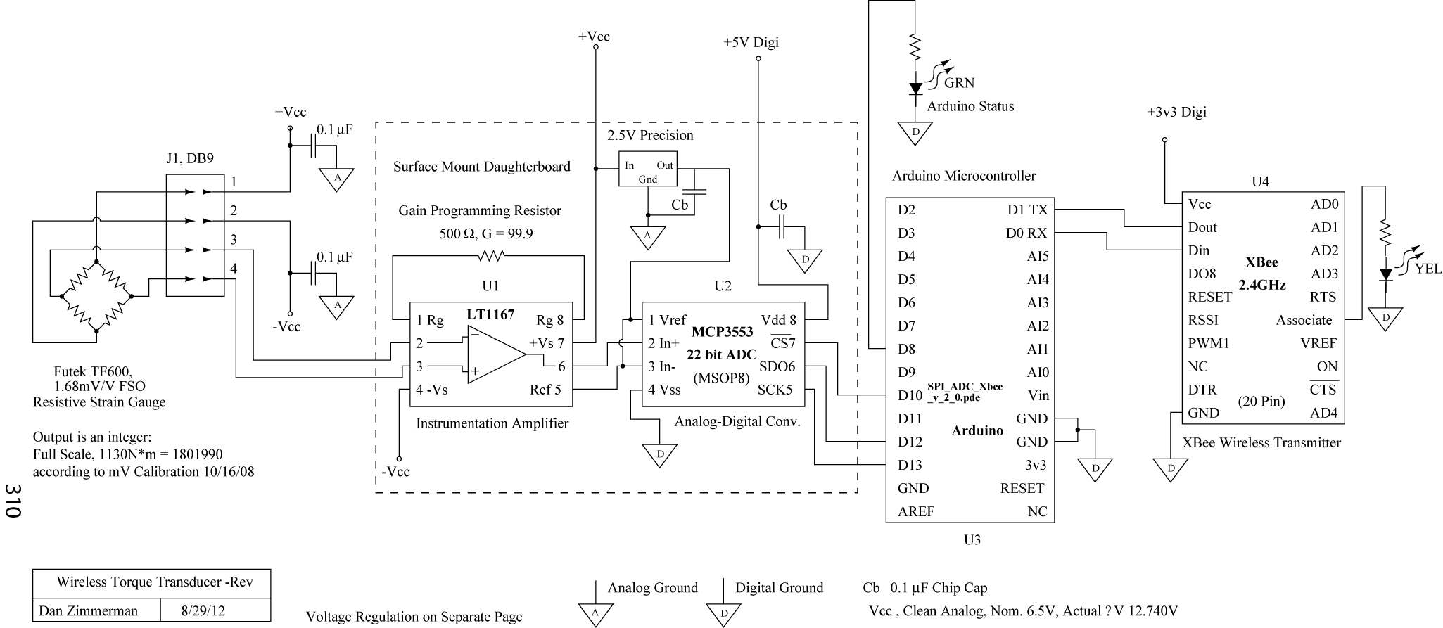
Schematic – [PDF Version]
Sensitivity and Noise
This sensor's full-scale reading is a massive 1130Nm but despite this, it is capable of registering light fingertip pressure on the torque load cell. The attention to low-noise design is part of this excellent performance. The plot below shows the output acquired by the torque sensor circuit when fed with a slow 50μV amplitude sine wave. I was feeding the strain gauge input with a 5 milliHertz 50mV sine wave from a precision signal generator attenuated 1000:1 with a voltage divider.
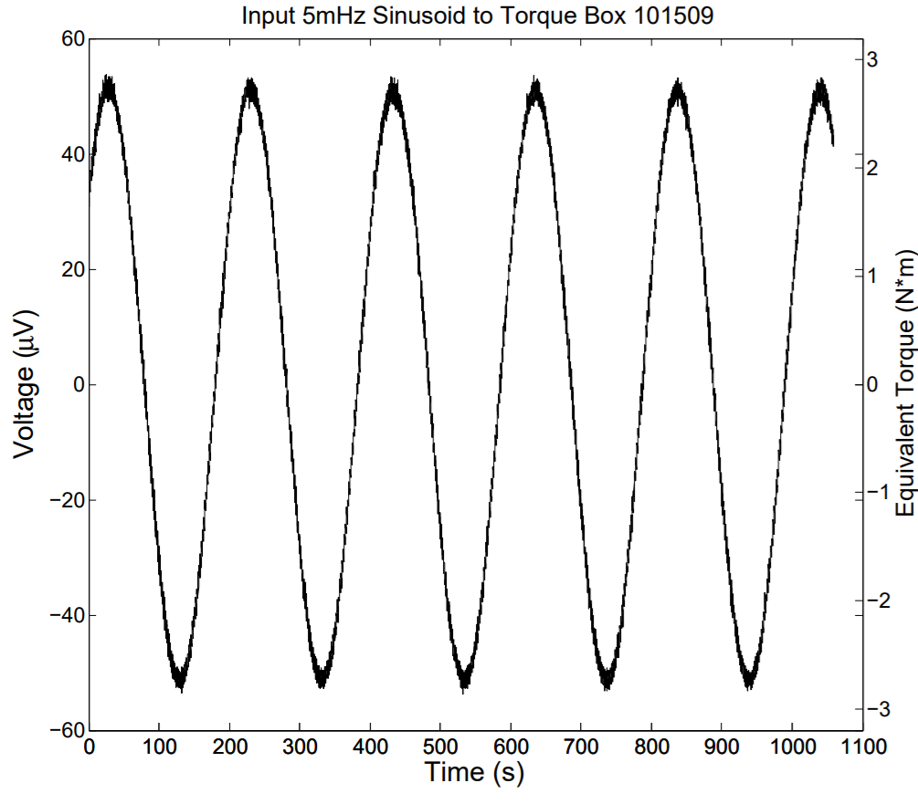
Noise testing - 50μV signal voltage
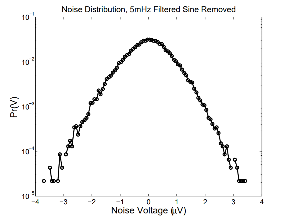
The probability distribution of output noise after subtracting out the 5mHz sine wave is shown below. Digitizing the torque sensor with this level of sensitivity might seem excessive given that the accuracy and linearity of the sensor itself are specified at something like 0.5% of full scale. However, the sensor is capable of registering dynamic fluctuations much smaller than that. The very wide dynamic range of this system allows qualitative insight into very subtle torque fluctuations around the extremely high mean torques, even if the absolute accuracy of the measurement is in question.