Background
I've held a ham radio license (N3OX, formerly N3UMH) for a couple decades. I've never worked professionally in RF engineering, but over the years I've executed a lot of substantial RF circuit design and antenna projects. As I've pursued my scientific career, I've applied more theory, mathematics, and testing rigor to my hobby pursuit, and as a result, I've got a lot of experience with low noise and high frequency analog electronic design, electromagnetic interference mitigation, and antenna design. I've picked a few projects to highlight here, with some more links at the bottom of the page.
Mechanically Tuned Electrically Small Antenna
I've designed, built, tested and used a lot of antennas over the years. This design is probably my all-time favorite because I put a simple, novel twist on an old standard and added a lot of functionality. It is an efficient, electrically small loaded monopole antenna for the 40m band (7.0-7.3MHz) with a compliant mechanical tuning system. This antenna is about 0.07 wavelengths tall, less than a third the height of a typical 1/4-wavelength monopole.
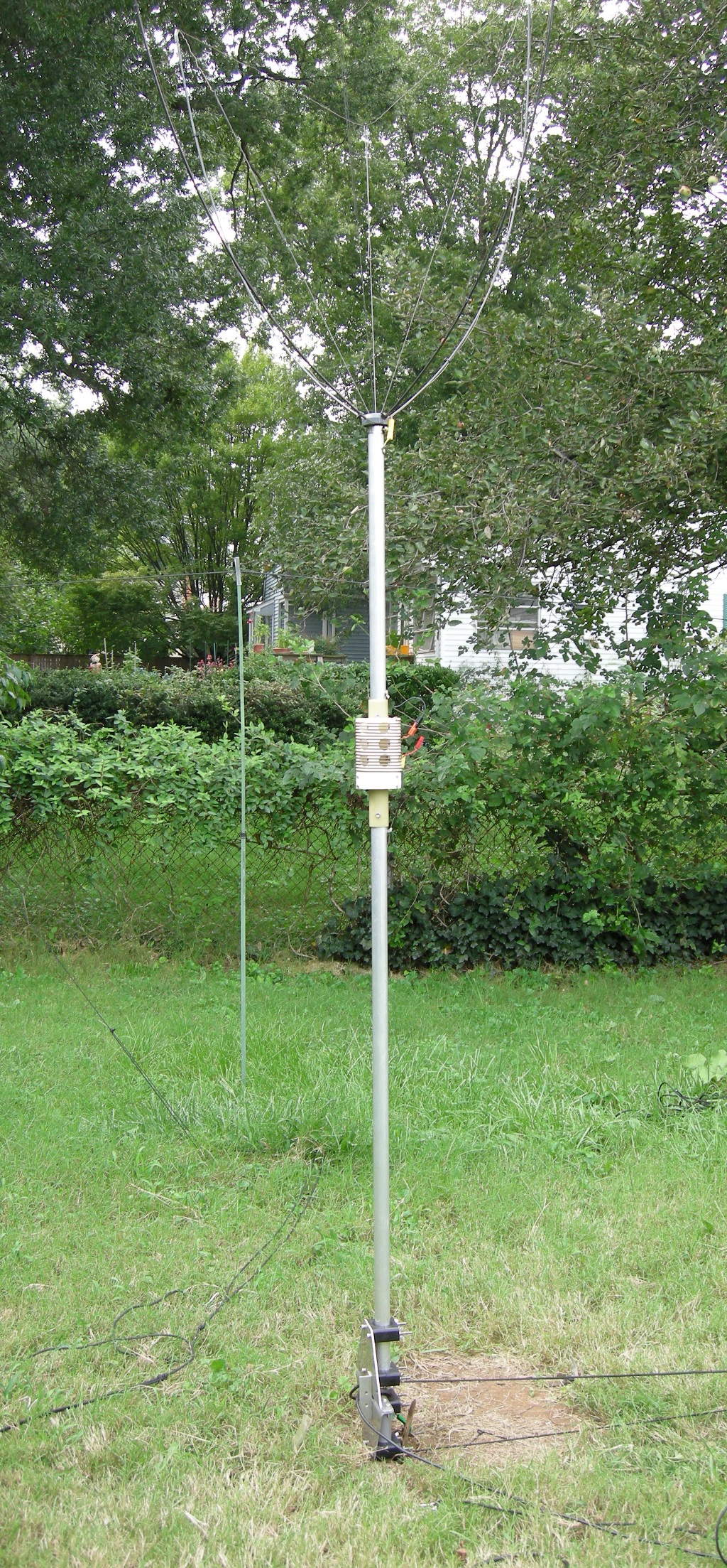
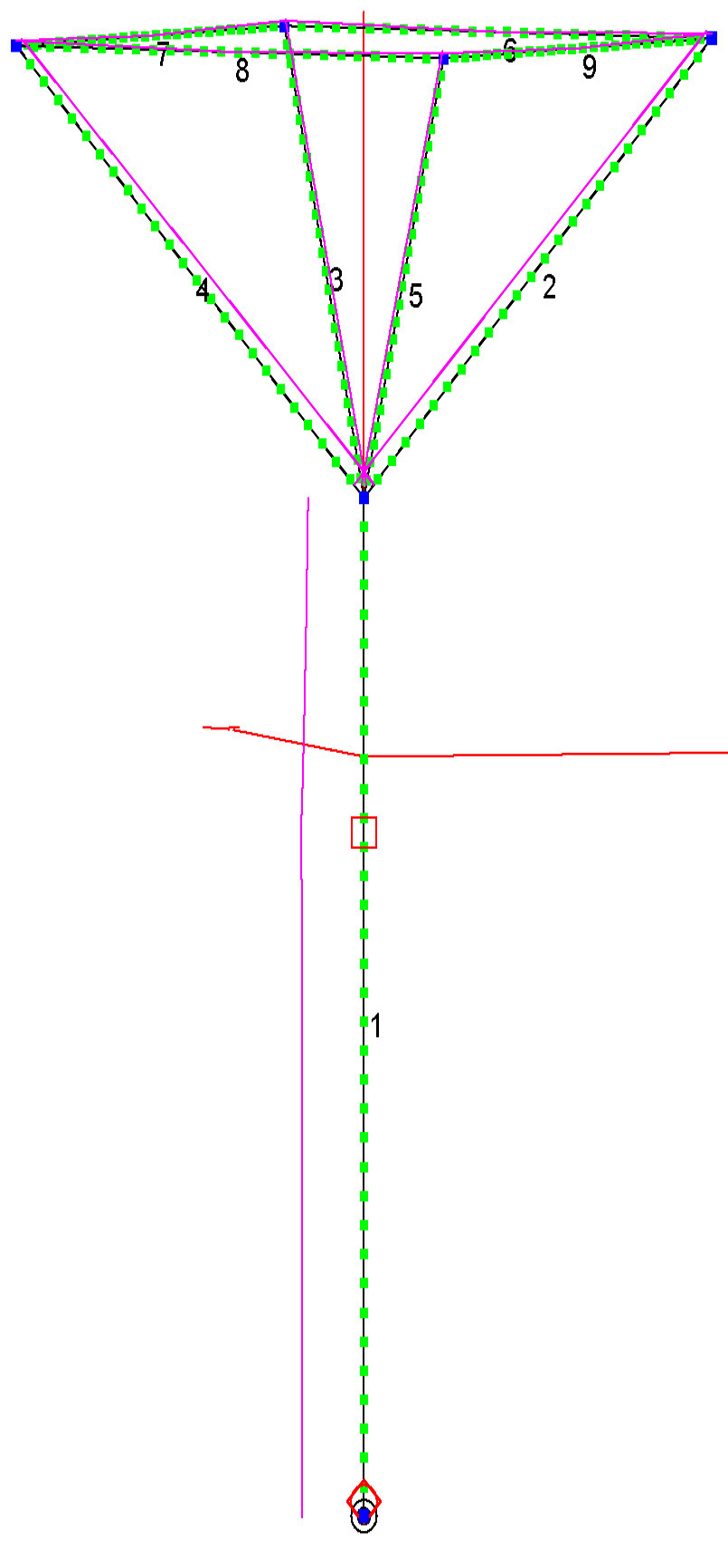
Fabricated antenna (left) and NEC-2 simulation (right)
The antenna is mid-loaded with a low-loss air-core inductor and heavily top-loaded with a pyramid-shaped capacitance hat made of wire on flexible fiberglass supports. Electrically small antennas have a fundamental tradeoff between bandwidth, physical size, and radiation efficiency. The main novelty of this antenna is the ability to mechanically change the effective capacitance of the hat to ground. This tunes the antenna to a desired operating frequency:
Mechanical capacitance hat tuning in action
The antenna has a mechanical tuning range of 7-8MHz, easily covering the entire band despite a 2:1 SWR bandwidth of about 72kHz at any fixed tuning. I later added a mechanically-actuated band switch which changes a tap on the inductor to resonate the antenna on the 10.1MHz amateur band when it reaches the top of the 40m band tuning range.
I used this antenna routinely for ham communications, but I also carried out a substantial project of NEC-2 modeling and near-field reception field-strength measurements to characterize its performance. The plots below show the measured and modeled complex impedance and the estimated dB loss compared to a full-size quarter-wavelength monopole. Because I could not directly carry out far-field measurements on this antenna, I used NEC-2 modeling to help me interpret the raw field strength results by computing the expected near-field coupling between my reference signal source and my antennas under test.
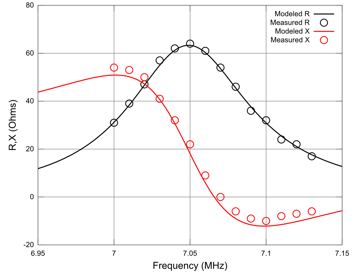
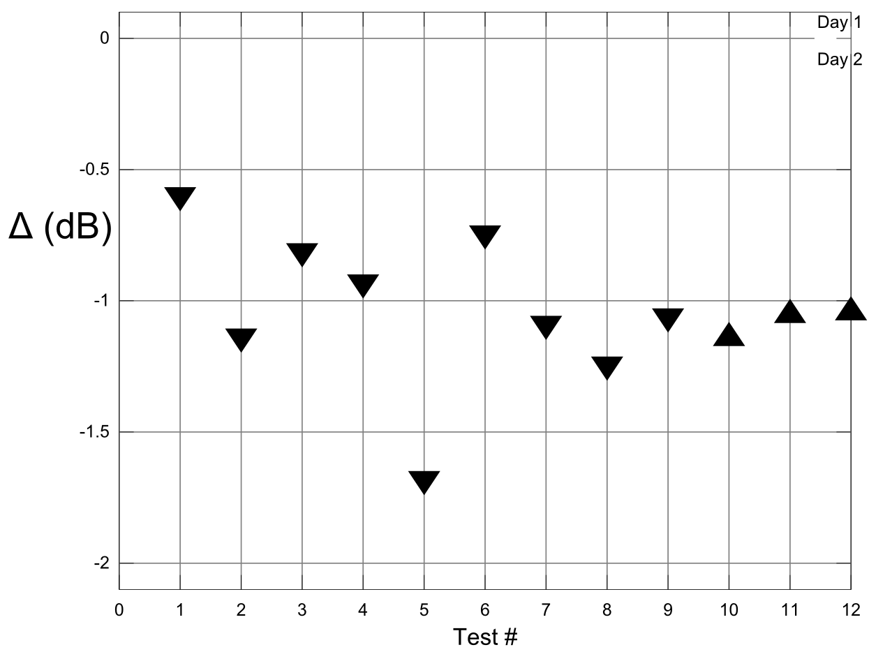
Modeled and measured impedance (left) and equivalent far-field dB loss vs. a 1/4λ monopole (right)
I've written up a full report on the design, fabrication, modeling and measurements at http://www.n3ox.net/projects/n3oxflex.
Coil ESR Characterization
During the testing of my flexible tuned antenna, I noted substantial signal attenuation caused by moisture on the loading coil. I couldn't find any quantitative data about wet RF inductors, so I set up an experiment to characterize the coil's equivalent series resistance (ESR) with and without moisture present.
I connected the coil under test in series with a low-loss vacuum-variable capacitor and used the resulting series LC circuit as the shunt element in a T-network attenuator. The maximum depth of the attenuation null achieved when the LC network is at resonance directly depends on the ESR of the coil and capacitor. Exact resonance is easily found by nulling the signal, since any reactance substantially increases the shunting impedance and sharply reduces the signal attenuation.
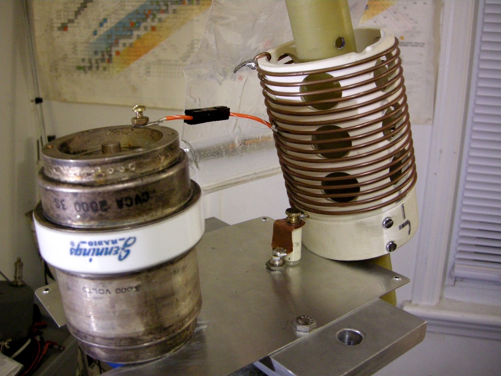
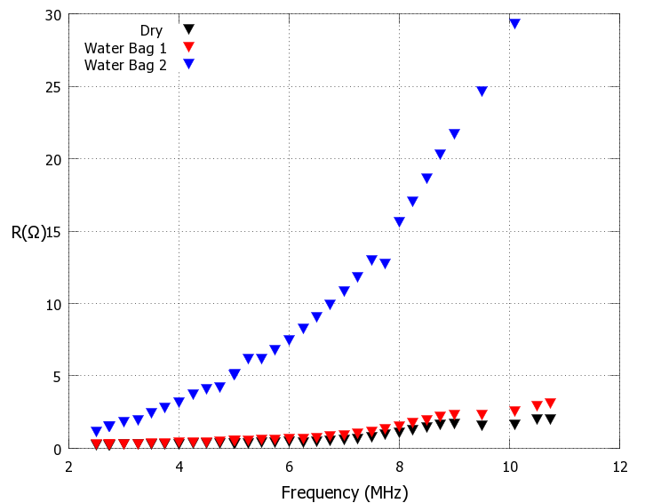
Coil ESR setup (left) and ESR results (right)
With a sufficiently low-loss capacitor like the one I used, most of the ESR can be ascribed to the coil, and the technique at least provides a worst-case number for the coil ESR. I then introduced bags of water near the coil and wet the coil directly to compare to the dry base case. The full report and a number of other coil tests are described at http://www.n3ox.net/tech/coilQ.
Computer-Switched Matching Networks
My typical winter antenna for the 1.8, 3.5, 7.0 and 10.1 MHz amateur bands was a 60 foot tall wire vertical with base-matching networks. I designed and built a computer-controlled motorized switch for this antenna to automatically switch to the appropriate matching network depending on the operating frequency of my transciever.
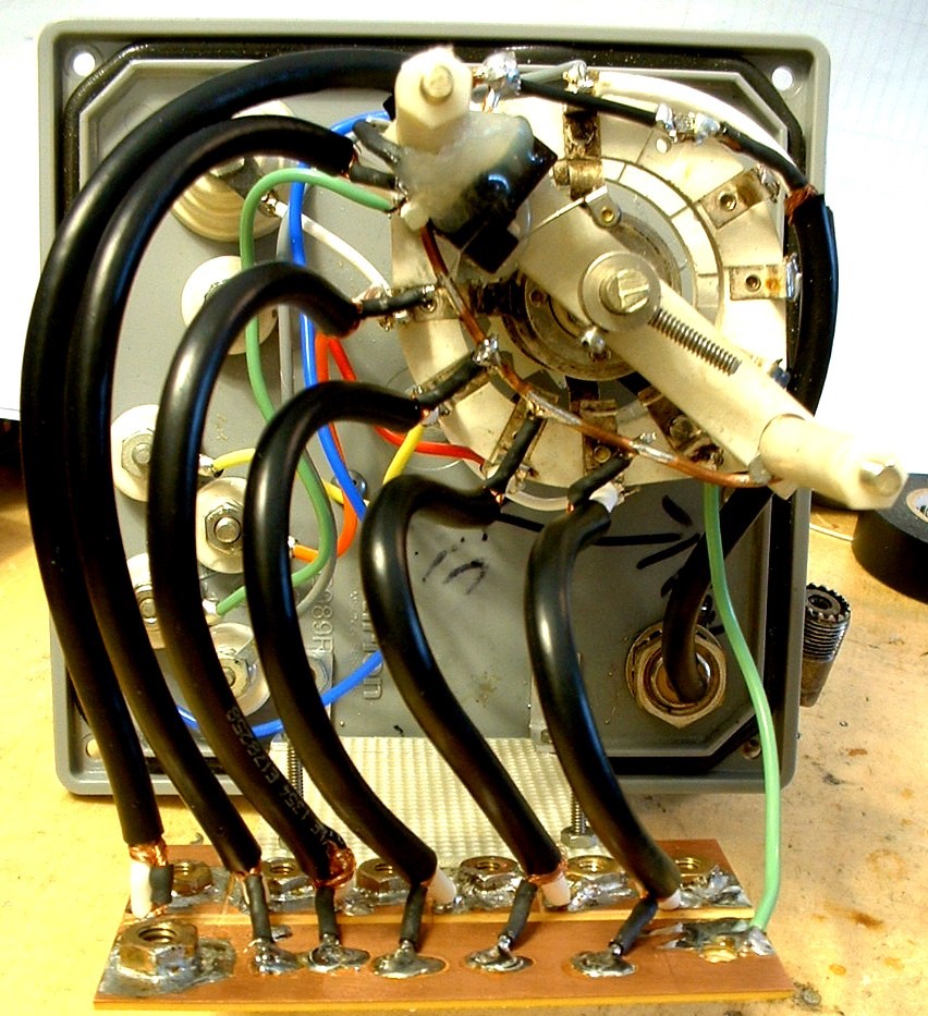
Switching unit interior (left) and matching networks (right)
The matching system included single fixed-tuned LC matching networks covering the 30m and 40m bands, a pair of networks to cover the 3.5-4.0MHz range (known as the 75/80m bands), and a continuous-tuned network to cover the 160m band where the antenna had a narrow useable bandwidth. A fixed inductor in series with a low loss 2000pF vacuum capacitor was used to adjust the 160m tuning across the 1.8-2.0MHz frequency range.
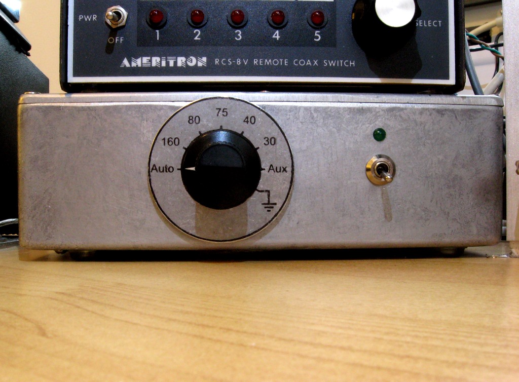
Matching switch control box
The motor driver and microcontroller were housed in the indoor control unit shown above. The control unit could be used as a manual band switch via the front panel control, or placed in automatic mode, where serial communications among the switch, my station computer and my radio would auto-switch the operating band. When the antenna was not in use, the vertical element could be directly grounded through the switch. An added feature moved the switch halfway between contacts to completely disconnect the radiating element from the matching networks and the coax. This was used on some bands to spoil the transmitting antenna's resonance during reception to minimize interference with the separate receiving antenna.
The project is described in more detail at http://www.n3ox.net/projects/stepperswitch/ and the switch's Arduino microcontroller code is hosted on GitHub.
1.8MHz Class-C MOSFET Amplifier
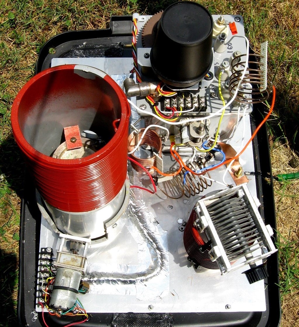
I built a 400W-output solid-state amplifier for the 1.8MHz (160m) band using $4 power MOSFETs as the active devices. These devices are not designed for linear RF amplification use, but my typical operations on this band used on-off-keyed Morse code, which can tolerate substantial amplifier nonlinearity. The amplifier has a pair of N-channel IXYS MOSFETs that alternately pull current through the primary of a ferrite RF transformer. The output is filtered with a diplexer-style lowpass filter to attenuate harmonics.
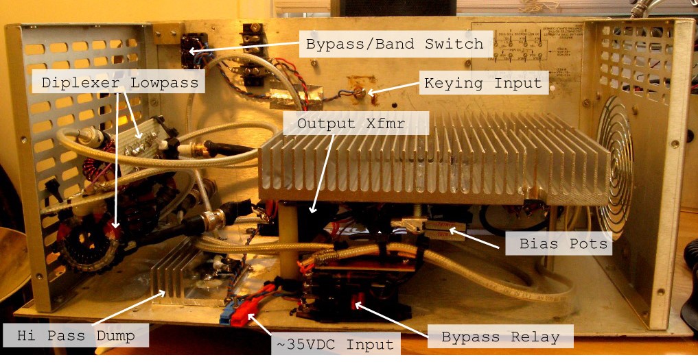
1.8MHz amplifier built with low-cost MOSFETS
The diplexer filter uses a high-pass filter and low-pass filter in parallel to pass the desired signal to the antenna and the undesired harmonic content to a termination resistor. The filter then appears as a broadband resistive load at all frequencies and dissipating the harmonics in a dump resistor increases the stopband attenuation, both of which are desirable in this application.
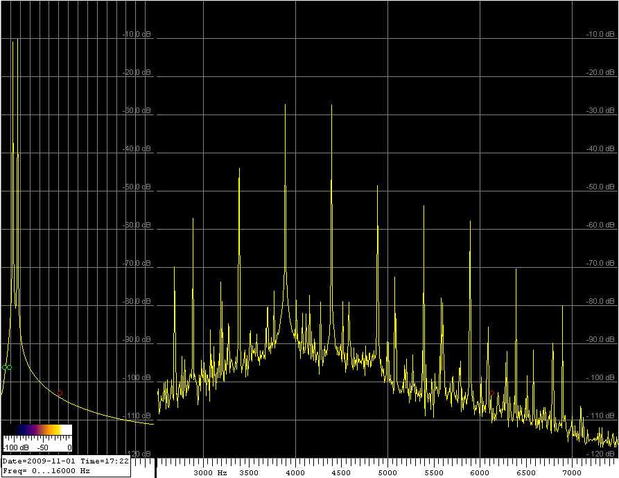
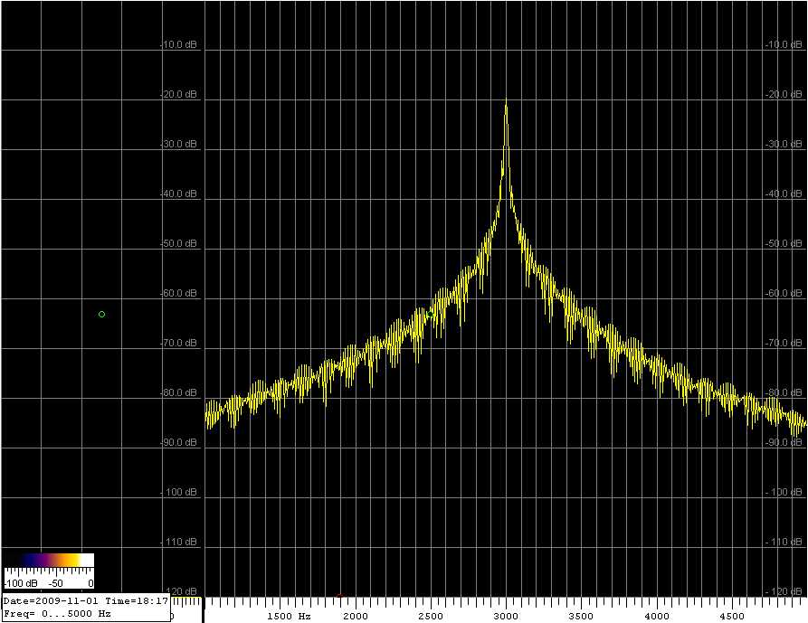
Two-tone distortion test at 350W output (left) and 20WPM Morse keying bandwidth (right)
I performed some spurious emission testing on my completed amplifier. A perfectly linear RF amplifier when fed with two continuous audio tones will generate two continuous RF carriers. Nonlinear mixing creates RF tones of other frequencies. The image on the left above shows the result of a two-tone test I performed to characterize the intermodulation distortion of this amplifier.
The image on the right shows the occupied bandwidth of a string of Morse dots sent at 20WPM speed. The 160m band supports very strong short-hop nighttime propagation, and domestic signals from low power stations are routinely 40dB+ above the noise floor. Weak distant stations right at the noise floor are easily overwhelmed by spurious emissions outside a reasonable occupied bandwidth, so I wanted to characterize the quality of my amplifier before I used it on the air.
Antenna Radiation Animations
I made some GIF animations of the time-dependent electric and magnetic field around several different antennas using NEC-2 simulations and GNU Octave. I computed the near-field E and H fields' magnitudes and phases on a grid around the antennas a few wavelengths across using EZNEC. I then exported this amplitude and phase information to render wave propagation animations as colormaps in Octave. The image below visualizes the fields around a five-element Yagi-Uda antenna mounted 100 feet above reflective earth.
Animated electric and magnetic field
The electric field pointing in and out of the page is shown in the top plot, and the magnetic field in the elevation-angle polar direction is shown in the bottom plot. The line drawing in the caption shows the far-field elevation radiation pattern of the antenna computed using the EZNEC model. The colormap has nonlinear compression like sign(E)*|E|1/5 so that more detail is visible in the field far away from the antenna.
Other Antenna and RF Links
N3OX Website
- Main Amateur Radio Page
- Rotatable Variable-Termination Flag Antenna
- Dual-Band Switched LC Beam Antenna Design
- More Antenna Radiation Animations